Inputs
Balanced and floating inputs are standard on the V700 modules. However, some units, like the faders and pan-pot modules for use in custom build consoles have electronically balanced inputs and outputs. Microphone inputs are always balanced and floating.
Balanced and floating Line Inputs:
- Nominal Level + 6 dBu
- Maximum Level >+ 30 dBu - Gain
- Input Impedance > 5 kOhm
- Input CMRR > 60 dB according to IRT
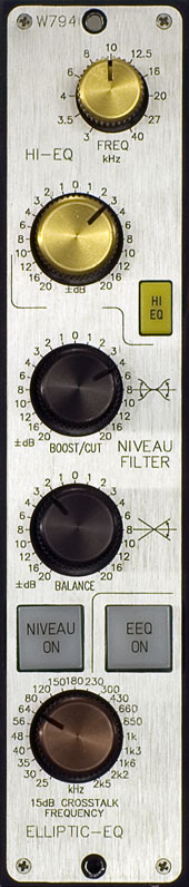
- typical value 74 dB bei 15 kHz
- Transformers:
- Haufe made tororial transformers
Balanced and floating Microphone Inputs:
- Maximum Level >+ 30 dBu - Gain
- Input Impedance >> 1 kOhm
- Input CMRR > 70 dB according to IRT
- Haufe made transformers
Electronically balanced Inputs:
- Nominal Level + 6 dBu
- Maximum Level >+ 30 dBu - Gain
- Input Impedance > 10 kOhm
- Input CMRR > 70 dB
- (by manual adjustment)
Outputs
Balanced and floating outputs are standard on the V700 modules. Transformers manufactured by Haufe or Lundahl are used. Some modules for use in customized consoles have electronically balanced inputs and outputs. This concerns, e. g., fader units and pan pots as well as zero ohm output for summing rails.
Balanced and floating Outputs:
- Nominal Level + 6 dBu
- Maximum Level >+ 30 dBu
- (with kges 1 % and 40 Hz)
- Load Resistance > 300 Ohm
- Source Impedance < 40 Ohm
- CMRR according to IEC > 40 dB
- CMRR according to IRT > 60 dB
- Transformers Haufe or Lundahl made
Electronically balanced Outputs:
- Nominal Level + 6 dBu
- Maximum Legel >+30 dBu - Attenuation Load Resistance > 600 Ohm
- Source Resistance < 40 Ohm
- CMRR according to IEC > 40 dB
All data is valid within the transmission band.
Crosstalk
- Within the transmission band crosstalk is typically:
- Between independing Signals >95 dB
- Between Multi-Channel Devices
- (Stereo or 5·1) >70 dB
- in MS-Direction Mixers > 40 dB
Level
Nominal Level + 6 dBu
Any other nominal level can be choosen. Unless otherwise stated, data refers to: 0 dB = 1.55 V = + 6 dBu.
Gain/Attenuation
Nominal Tolerance ± 0.3 dB
This tolerance applies to calibrated scales points, like 0 dB points of faders, center detends of rotary gain controls and as well as other level adjusting controls like stepper switches.
|
Headroom
Headroom >+ 30 dBu
The headroom for all devices is >+30 dBu at inputs and outputs - depnding ont the setting of gain or attenuation. The value of + 30 dBu applies to a harmonic distortion of kges >1% in the transmission band and is typically 0.3 % at + 30 dBu and 40 Hz. The observance of the value assumes the correct setting of the power supply voltages. *1
Dynamic Range, Signal to Noise Ratios and Noise Level
The noise level of the processing devices is specified in the module specific data sheets. The majority of the V700 modules have an dynamic range of more than 120 dB RMS (22Hz to 22 kHz), at a nominal level of + 6 dBu with 24 dB headroom and 96 dB signal to noise ratio. The IRT demands with regard to the operating characteristic are excelled in all gain ranges.
Master Outputs
The signal to noise ratios for masters and groups depend on the number of channels beeing used. In the V700 system a balanced zero ohm summing system with very low impedance mixing resistors is applied that offers excellent noise performance.
Microphone Preamplifier
With more than 70 dB of gain the noise figure is > 1 dB (200 Ohm source, less than -117 dBqp input referred).
With 45 dB of gain the noise figure is < 2 dB (200 Ohm source, less than -116 dBqp input referred).
Harmonic Distortion:
kges < 0.1 %
Within input and output levels up to +26 dBu within the transmission band the maximum harmonic distortion with the nominal load resistance ammounts to 0.1 %.
For devices equipped with transformers the distortion coefficient k3 rises at 40 Hz up to a level of + 30 dBu at maximally 1 % . The typical value for the THD at 40 Hz and + 30 dBu is 0.3 %. The Haufe und Lundahl tranformers have saturation levels of >> + 30 dBu at 40 Hz.
With regulation amplifiers the harmonic distortion is determined by the setting of the release and attack parameters.
Frequency Response
For any modules at nominal level, without any processing stages that affect or modify the frequency response:
20 Hz bis 20 kHz ± 0.25
The normally integrated RF- and subsonic filters attenuate frequencies above 100 kHz and below 10 Hz. In the standard version the attenuation at 200 kHz is - 4 dB and the attenuation at 5 Hz is - 2 dB. Above 100 kHz and below 10 Hz the signal level rises by resonance effects not above 0 dB values. Modules that are produced according to the IRT rules are kept within the specified frequency range of 15 Hz to 40 kHz. The filters can be tuned differently for custom versions.
For microphone amplifiers a more effective filtering is employed because of the high sensitivity of the microphones and cables to subsonic disturbances and RF irradation. The following data is valid for all gains from 0 to 80 dB.
40 Hz to 15 kHz ± 0.5 dB
20 Hz to 20 kHz + 0.5 / - 1.5 dB
Attenuation at 5 Hz > 6 dB
Attenuation at 200 kHz > 10 dB
Modules produced according to the IRT directives have a blocking attenuation of > 20 dB at 40 kHz and > 12 dB at 15 Hz.
|