

U795 Stereo Mastering Limiter with analog Delay Line and dynamic Release Time Modulation Here are all details on the analog delay and the Stereo mastering Limiter adt-audio's dynamic Release Time Modulation allows higher gain reduction by compensating the negative, audible side effects of any limiting with more than 3 dB of gain reduction effectively. The LF modulation of the release time can increase the release time depending on the low frequency components. Bass distortion due to short, pump-free release setting can be avoided with an appropriate setting. The Peak Release modulation makes possible to fade out small and fast peaks with very short release times. An additional detector reacts to such peaks and drives the release time down, just for the time of the peak. This circuit avoids that a small peak over a bass signal causes audible pumping. Dynamic Release Time Modulation While the analog delay line makes it possible to raise the input level of the a/d converter to practically 0 dBFS and reduces the need for using digital limiters, the limitations of the maximum possible gain reduction are still exisiting. The most criticle parameter is the release time. If the release time is short enough to avoid audible pump up effects, the regulation is so fast that low frequency signals are controlled within the cycle time of the LF signal, which causes low frequency distortion. The tolerance range is very small and becomes smaller with higher gain reductions, due to the effect that the release time increases with the gain reduction. Finding the compromise between pumping and distortion results in the practicle limitation for the gain reduction of 3 dB for usual mixes. The Stereo Mastering Limiter U795 has two independent circuits to reduce the audible side effects of higher gain reductions: Low Frequency Release Time Modulation The frequency depending release time modulation of adt-audio uses a second ac/dc converter, which is combined with a special filter that simulates the increase of distortion at low frequencies and generates an additional control signal that is proportional to the portion of distortion sensitive low frequency components above threshold. An analog computation circuitry that considers the settings of threshold and release calculates a correction value for the release time that avoids LF distortion. This signal drives the RATIO LF RELEASE control, which is designed in way that the total range allows overcompensating the distortion. To put it in a nutshell, as soon as low frequency distortion can occur, the modulation circuit turns the release control to the right to increase the release time, which avoids distortion. As soon as the LF signal is down again, the automatic returns the release control to the old value. With an appropriate setting of the RATIO LF-RELEASE control, it is possible to compensate the LF distortion precisely, which results in a higher possible gain reduction. The MAX control of the LF release modulation circuit allows to limit the maximum possible release time to a fixed value. This control should be all to right to allow maximum control range in the beginning. It is useful with mixes that do not have rather constant LF signals. A very high LF signal, e. g. during a drum break, can cause a control signal that is a lot higher than the average and might shift the release to a long value that results in audible pumping for a short time right after the LF signals. In cases like this, the MAX control allows to limit the release time to a value that is still pump free. The ADJ (adjust) switch applies a control signal to the LF circuitry that simulates a 100 % LF signal. The switch can be used to set the max control, without the need to check the program for the occurence of such 'pumping from overcompensation' effects. For normal operation, the switch has to be released, or the release time will remain at the high setting and no regulation takes place. The function of the circuitry is displayed by a 3-color LED indicator. Green color shows that no regulation takes place. The color changes to yellow with regulation and changes via orange to red proportional to the intensity of regulation. |
|
||||||||||||||||||||||||||||||||||||
|
The Peak depending Release Time Modulation This release time modulation is controlled by the slew rate of peak signals. An third converter circuit checks the structure of the envelope of the signal and reacts to high slewrate peaks that are above threshold using a complex differentiation process that calculates not only level and slew rate but also the duration of the signal. The output signal of the analog computation circuit is used to reduce the release time during the peak. This covers the problem of peaks above high level bass signals. The release time during the high level bass signal is increased by the LF modulation circuitry to avoid distortion. However, this results in a release time that is above the 'pumping threshold' for the time the LF signal is present. A peak will now cause regulation that recovers with exactly that release time and pumping becomes audible. If the release time would be short just for the time of the peak, this effects can be avoided. The control signal is available at the RATIO PEAK RELEASE control that allows adaption of the modulation to the audio signal. Like with the LF modulation circuit, the modulation can be limited. The MIN control allows adjusting the minimum release time that the modulation can adjust. If the RATIO PEAK RELEASE control is well adjusted to peak signals over bass signals, no pumping or distortion will be audible. However, overcompensating results in a short release time that lasts longer than necessary for the peak. If the peak signals are not almost constant during the mix, it can happen that an adpated setting causes such effects somewhere in the mix. Adjusting the minimum release time with the MIN control solves this problem. The ADJ switch operates based on the same principle as the corresponding switch in the LF modulation section. Pressing ADJ applies a test signal to the circuit that is equalvalent to the highest signal that the peak detection circuitry can deliver. This can make the adjustment of the MIN control easier. After adjusting, the ADJ switch must be released or the minimum release time will remain valid and no regulation takes place. An additional LED indicator displays the effect of the peak regulation. With green color, no regulation takes place; yellow shows regulation and orange to red lets you determine the level of regulation. Due to the short duration of the peaks, the display has a short hold time that is not applied to the release control circuitry. This hold time is necessary to make the regulation visible on the LED indicator. |
|||||||||||||||||||||||||||||||||||||
 V700
V700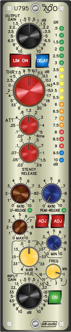
| U795 Information: | ||
|