|
- Integrator Cassette Module Housings
There are 3 versions of the Integrator module housings. The 4U high cassette is used for all kinds of devices. Some units are available as compact versions in a 3U high cassette as well. The 6U high cassette is used for all the input channels and master modules of the fader frame.
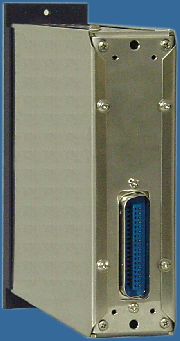
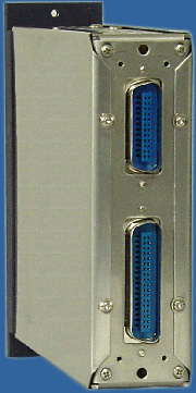
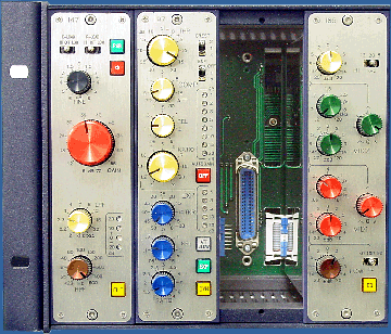
- For almost all processing units, input amplifiers, control-room modules, meters, accessories and the C41 Cascade mixer unit, the 4U high cassette is used. Depending on the necessary connections of the particular module, an additional connector is installed or not. If a module has this additional connector, it must be installed in the slot 9 of a 4HE-Frame/s to use all the features. These units work in a standard slot, but not all the inputs and outputs are available. For a control-room regulator this means, that you can not connect the additional speaker outputs Alt and Mini, but you can use the main input and output in a standard slot. These limitations are not valid with the 4HE-Frame/e.
|
|
 |
|
|
|
 |
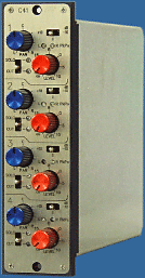
- The 4U cassette is 168 mm high and 220 mm deep. The 3U casstte is 122.5 mm high and also 200 mm deep. The 6U high mxing modules are 257 mm high and 120 mm deep. The pictures on this page show the C41 Cascade compact mixer and the 4 band equalizer I85 as examples for the 4U cassete in different views. The single slot module is 45.7 mm wide.
- Like the V700 housing, the Integrator cassette top plates are made of 15 mm massive, anodized aluminum alloy. The fascia is made of anodized aluminum with engraved lettering. It is inlaid in a milled undercut and fixed with 4 screws. The fascia is available in several colors to allow easy adaption to the customer's taste. The standard version is grinded and anodized. For examples of other colors see the V700 page. Please consider, that web colors depend on you computer system and might be far away from the reality. Since the fascia is only fixed with 4 screws it can be exchanged easily. Just remove the screws, remove the fascia and fix the new fascia. The housing and all the screws are made of a chromium nickle stainless steel alloy. The gold plated connectors have a standard connection schema for all the power supply rails, the audio inputs and outputs and the control ports as well. All units require an audio supply voltage of +/- 25 V for optimum performance but work with slightly reduced headroom with any voltage above +/- 18 V. The difference in headroom between 25 V and 18 V is approx. 3 dB. Crosslinking of audio signals across the power lines is avoided by internal filters and low dropout voltage regulators. A separate 24 V Voltage for relais, lamps and other signalization equipment separates any click noise from the audio supply rails. Microphone Preamps require an additional 48 V Phantom Power Supply. The 6U cassette has two 50 pin connectors installed. In addition to the 6 available audio inputs and outputs, there are all power rails and all the necessary buss rails for mixing and control. The 3U cassette has a 50 pin connector while the 4U cassette basically has a 36 pin connector for power and the main stereo inputs and outputs. All the additional connections that are needed for several devices are placed on an additional 24 pin connector.
|
|


