

 |
|||||
 |
|||||
 |
|||||
| You are here: HOME-PRODUCTS-SURROUND-DYNAROUND | |||||
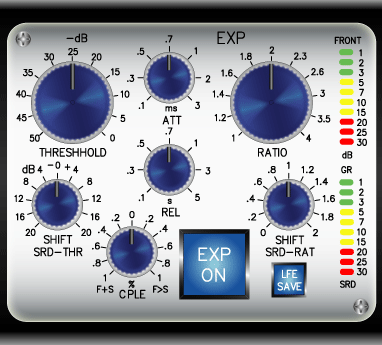
| The LFE Channel The LFE channels is used for the transmission of Low Frequency Effects and at best for the addional transmission of a subbass signal. Hence its importance for dynamic processing as well as for the location of signals is practically not existing. Though it has to be considered that the reality of a lot of speaker systems use the subwoofer principle for the simple reason that it results in lower cost and smaller speaker housings. The economical advantage of this principle is obvious, but the disadvantage, that the channel assignment of the 5.1 principle is turned inside out has to be considered. The subwoofer receives not only the LFE signal but also the portions of the other channels which are below about 300 Hz. This can cause considerable compatibility problems which are described in detail with the Dimensions surround direction mixer. It is not meaningfull to include the LFE channel into the production of the control voltages. This could lead to the low frequency regulating activity of the processors in a disturbing way. Therefore we have added a separate limiter path for the LFE channel. This uses the main level, attack and release parameters, but allows the limiter to process the LFE channel separately from the other channels. This feature is controlled by the LFE LIM switch. Also the standard in all 3 processing sections of the unit is that the processing of LFE channel is regulated by the front channels. This regulation automatically ensures that level conditions of the LFE channel are adapted to and directly relates to the front channels. But since this operational relationship cannot be standardized, and is for the most part program dependent, we have included an option that removes the LFE channel from each processor individually with the LFE OFF switch. The Surround ExpanderThe threshold of the expander can be adjusted between -50dB and 0dB, and the threshold of the surround channels can be offset by up to ±20dB. The ATTACK ranges from 100µs to 3ms, and the RELEASE has a range of control from 0.1 to 5 seconds. The ratio can be regulated between 1:1 and 1:4. The SHIFT control for the surround channels makes a variation between the factors for 0 and 2 possible. The interconnection ratio between the front and rear channels is adjusted by the CPLE control between 100 % F+C and 100 % F>C. In the central position, the front and surround channels operate independently of each other. Two 10 element, LED chain display systems, display the gain reduction for the front and surround channels separately. |
|||||
| The Realization For the realization of a 5.1 dynamic processing system we offer the following solution. All elements operate independently for the front and surround channels. The adjustments of threshhold and ratio are transferred from the regulation of the front channels to the surround channels. Two additional SHIFT controls can be used to offset the settings of the front channels to the surround channels. With this procedure the front and surround channels can be processed separately and the measure of coupling or offsetting can be determined as needed. We have taken this principle further with two additional COUPLE controls. When placed in the center position, front and surround channels operate as independent regulation amplifiers. When turned to the right, a mixing of the rule signal of the front channels and right-surround channel takes place; all to the right, the front control signal is completely coupled to the surround signal. If turned to the left, a mutual interconnection of both rule signals take place. At end position left, the system works as a normal multi channel rule amplifier with even evaluation of all 5 channels. The SHIFT controllers for threshhold and ratio work independently of this feature. All three processors of the DYNAROUND dynamic system operate on this principle. |
|||||
 |
|||||