
| OPEN IN NEW WINDOW/TAB | HOME | TOOLMOD PRO AUDIO | CLOSE | TM103 HOME | CONTACT |
Control Elements
active DI Amp - ToolMod Pro Audio - TM103
active DI Amp Home
| Control Elements | Details and Specials | |
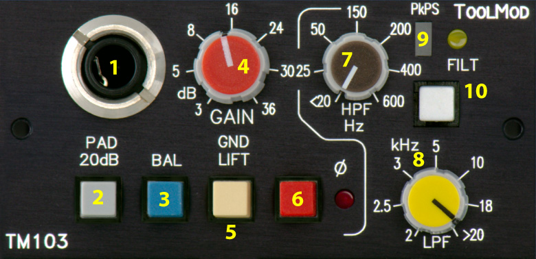
| 1 | TRS Input Jack (1/4") for Instrument - see Details and Specials for more |
Input Jack The TRS input jack is wired in parallel to the TRS jack 'OUT-b' and the female xlr connector 'IN-a' on the connector panel of the frame. This feature allows direct connection of the instrument to an amplifier without additional y cables. Pad unbalanced or balanced Mode Ground Lift IMPORTANT NOTE: |
| 2 | selects input pad of 20 dB - see Details and Specials for more |
|
| 3 | selects balanced mode the input is unbalanced if this switch is not pressed - see Details and Specials for more |
|
| 4 | Gain Control control range 3 dB to 36 dB |
|
| 5 | Ground-Lift switch, separates the TRS jack on the top plate from the internal ground - see Details and Specials for more |
|
| 6 | Phase Reversal |
|
| 7 | High-pass filter, control for the lower corner frequency, control range < 20 Hz to 600 Hz, steepness 24 dB/Okt. |
|
| 8 | Low-pass filter, control for the upper corner frequency, control range > 20 kHz to 2 kHz, steepness 12 dB/Okt. |
|
| 9 | Peak-present level indicator 3-color LED Green - level >= - 20 dB yellow - nominal level above nominal level, the color changes from yellow to orange and red. The remaining headroom with red color is about 5 dB. |
|
| 10 | FILT switch inserts the high-pass/low-pass-filter | |
| Sitemap |